For some time I have been planning to install at least one sensor on the Leigh bells so we can do some training with a simulator such as Abel.
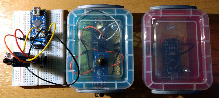
The picture above shows a prototype and two sensors that I have made. The prototype on the left has both a magnetic and infrared detector. The middle one is infrared and the one on the right is magnetic.
All the sensors use an Arduino Nano to continuously scan for a change in an input and the sending this via Serial/USB to a PC running Abel or another simulator program. I use a 10m active USB cable to connect the sensor in the bell chamber to the PC in the ringing chamber. This is just long enough for Leigh on Mendip tower (we have an upstairs ringing chamber with a clock chamber between the ringing chamber and the bell chamber). You can plug this straight into the PC and Abel will detect it as a serial port, just configure Abel to use the serial data not the signal lines. The USB cable provides the power to the Arduino so no power is needed in the bell chamber.
The code running on the Arduinos is very simple.
Arduino source code for the magnetic version.
/*
 Magsensor

 Magnetic proximnity sensor for bell simulator.

 */

// constants won't change. They're used here to
// set pin numbers:
const int sensorPin = 2;    // the number of the proximity sensor signal pin
const int ledPin = 13;      // the number of the LED pin

int sensorState = LOW;

void setup() {
  Serial.begin(2400);

  pinMode(sensorPin, INPUT);
  pinMode(ledPin, OUTPUT);

  // set initial LED state
  digitalWrite(ledPin, LOW);
}

void loop() {
  // read the state of the switch into a local variable:
  int reading = digitalRead(sensorPin);
  digitalWrite(ledPin, reading);

  if (reading != sensorState) {
    sensorState = reading;
    if (sensorState == HIGH) {
      Serial.print("1");
    }
  }
}
Arduino source code for the infrared version.
/*
 Irsensor

 IOnfra red sensor for bell simulator.

 */

// constants won't change. They're used here to
// set pin numbers:
const int sensorPin = 3;    // the number of the IR sensor signal pin
const int ledPin = 13;      // the number of the LED pin

int sensorState = LOW;

void setup() {
  Serial.begin(2400);

  pinMode(sensorPin, INPUT);
  pinMode(ledPin, OUTPUT);

  // set initial LED state
  digitalWrite(ledPin, LOW);
}

void loop() {
  // read the state of the switch into a local variable:
  int reading = digitalRead(sensorPin);
  digitalWrite(ledPin, reading);

  if (reading != sensorState) {
    sensorState = reading;
    if (sensorState == HIGH) {
      Serial.print("1");
    }
  }
}
Comments !